SBC/Beaglebone
Software
Hardware
Header References
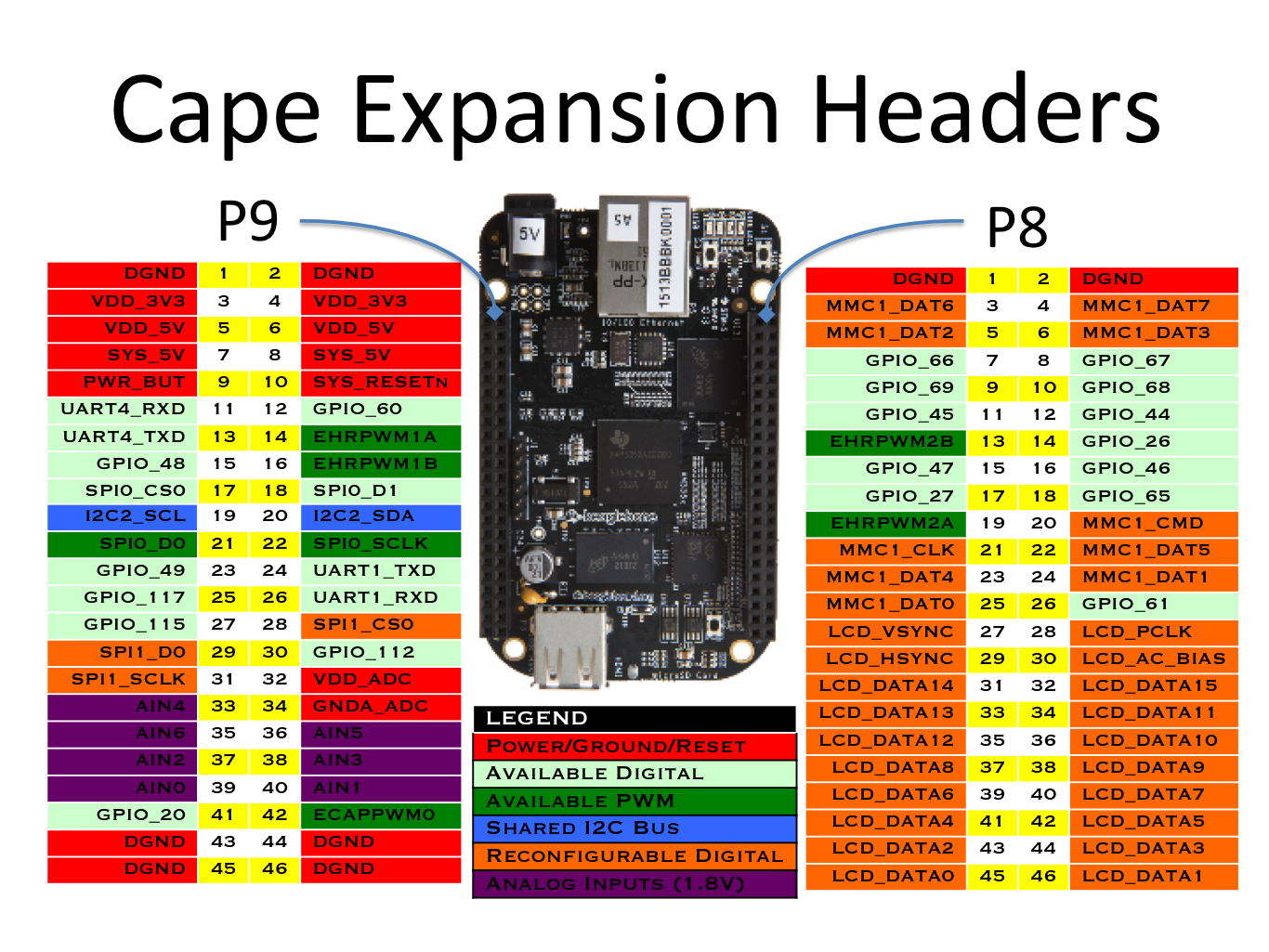
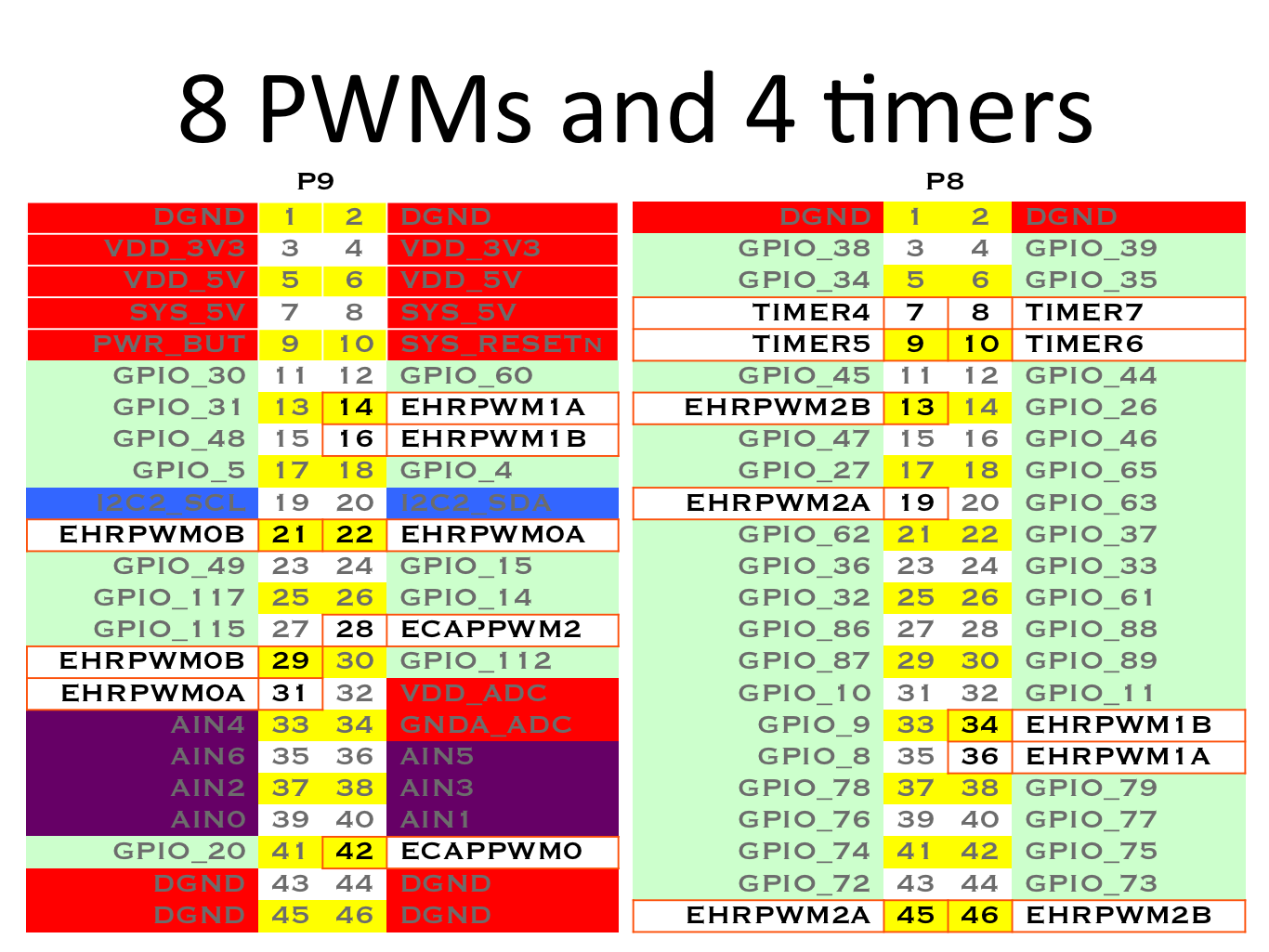
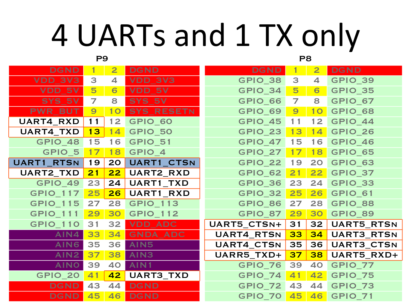
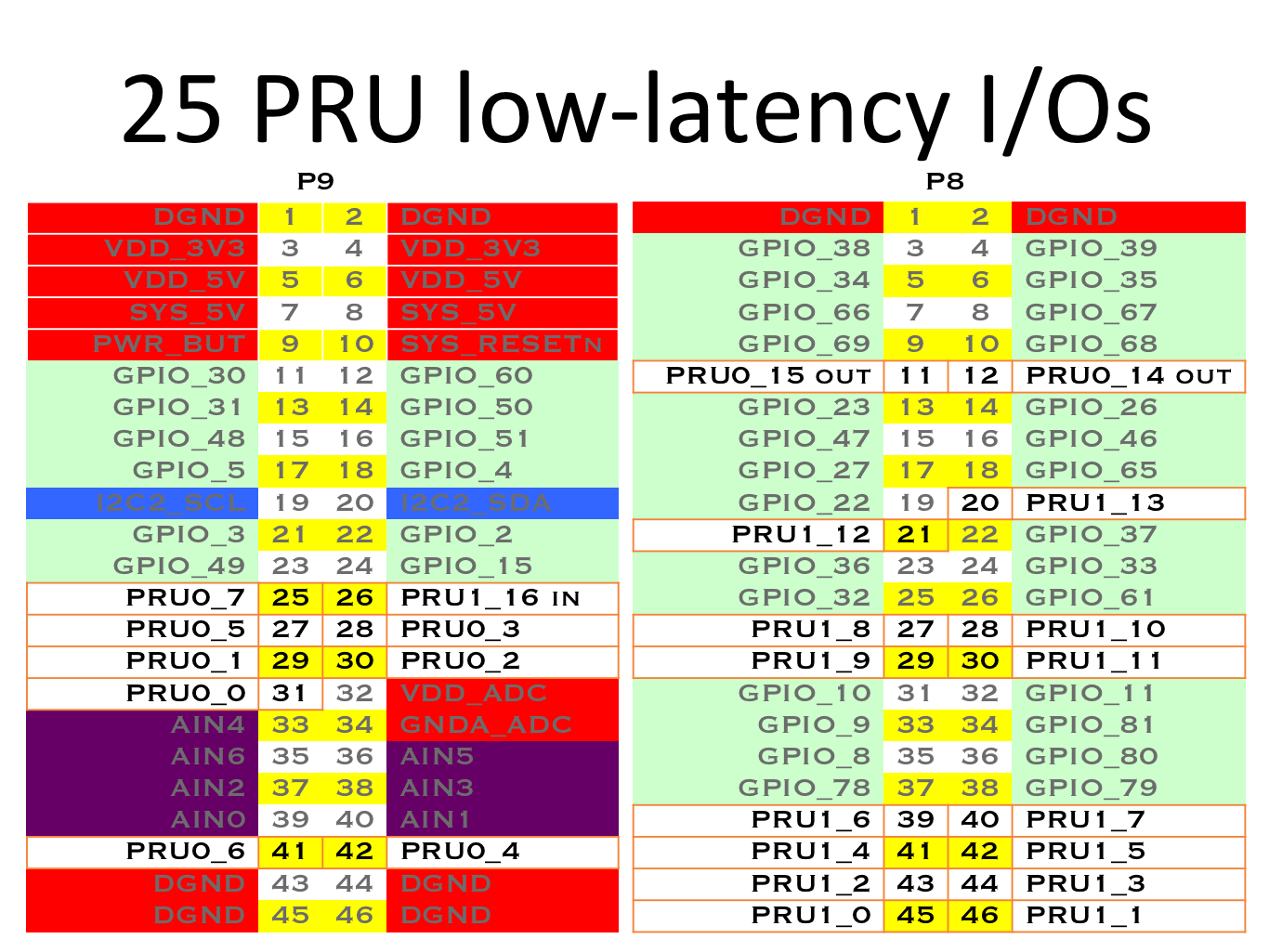
Input/Output (IO)
ADC
12 Bit
125 ns sample time
0-1.8V
2uA sample current
Overlays: BB-ADC
Sysfs Path: /sys/bus/iio/devices/iio:device0
Warning
Vmax on ADC is 1.8V
GPIO
3.3 V
Source 6mA, Sink 8 mA [2]_
Pins limited to sourcing 4mA: P9_19, P9_20, P9_24, P9_26, P9_41, P9_24
Internal Pullup/down resistors: 25K
Sysfs path: /sys/class/gpio
Note
GPIO number matches the export number under /sys/class/gpio.
EX: GPIO_66 = echo 66 > /sys/class/gpio/export
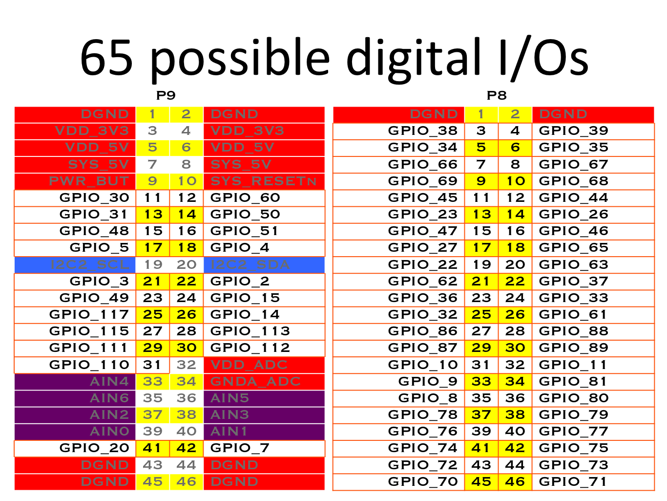
Default Configurations:
Header Pin |
Pin Name |
PU/PD |
|---|---|---|
P8_7 |
GPIO_66 |
PU |
P8_8 |
GPIO_67 |
PU |
P8_9 |
GPIO_69 |
PU |
P8_10 |
GPIO_68 |
PU |
P8_11 |
GPIO_45 |
PD |
P8_12 |
GPIO_44 |
PD |
P8_15 |
GPIO_47 |
PD |
P8_16 |
GPIO_46 |
PD |
P8_17 |
GPIO_27 |
PD |
P8_18 |
GPIO_65 |
PD |
PWM
xyz
Timers
xyz
Busses
I2C
Overlays: BB-I2C1, BB-I2C2
Note
I2C-0 is not exposed on headers
I2C-1 conflicts with SPI-0
External pullups required on SDA & SCL
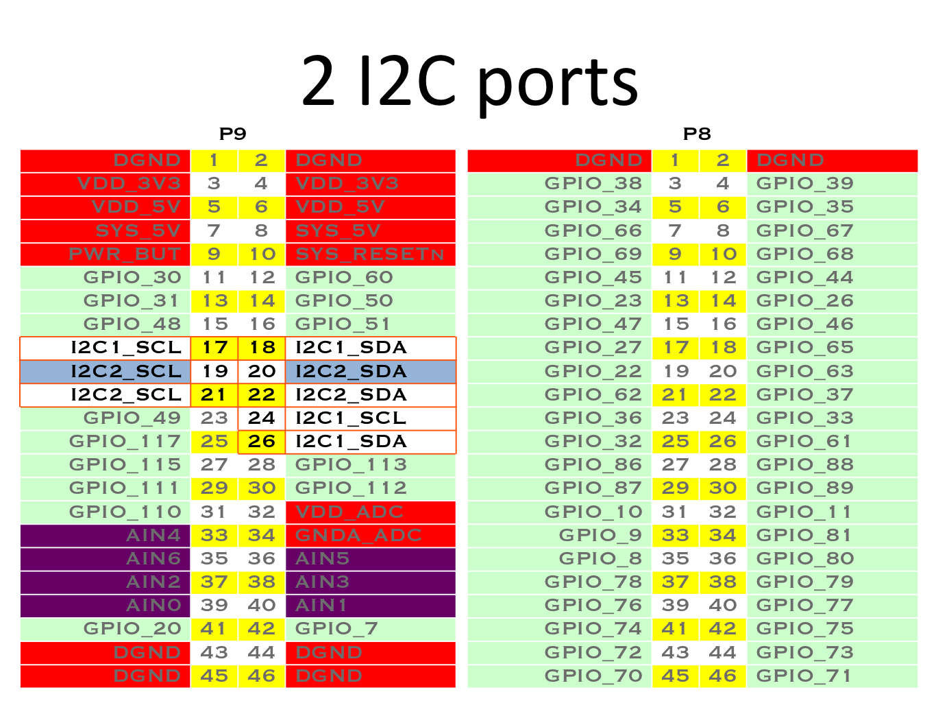
I2C1 |
I2C1 |
I2C2 |
I2C2 |
|
|---|---|---|---|---|
Signal |
Number |
Name |
Number |
Name |
SCL |
P9_17 |
SPI0_CS0 |
P9_19 |
I2C2_SCL |
SDA |
P9_18 |
SPI0_D1 |
P9_20 |
I2C2_SDA |
SPI
Overlays: BB-SPIDEV-0, BB-SPIDEV1
Note
SPI-0 conflicts with I2C-1
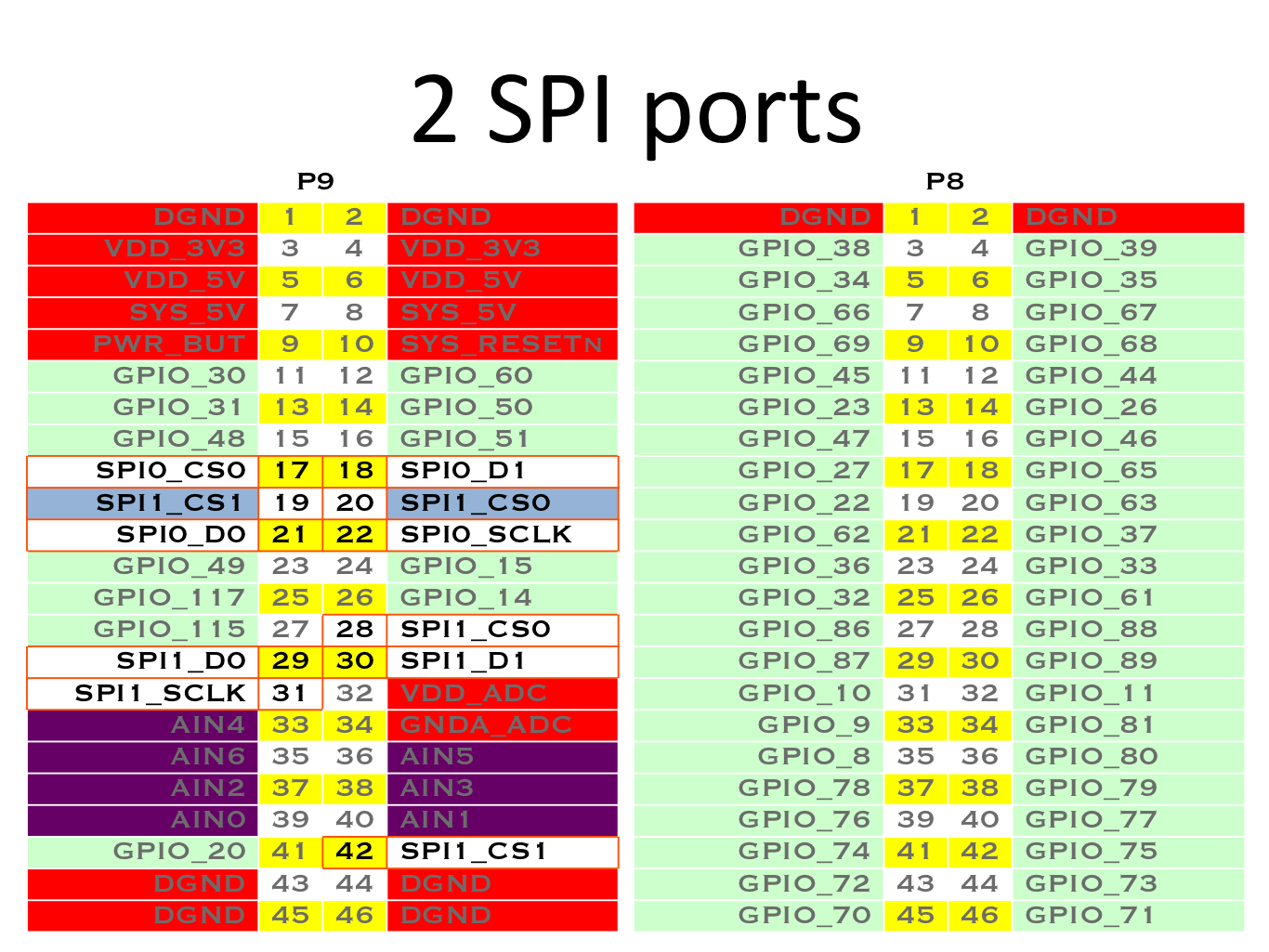
SPI0 |
SPI0 |
SPI1 |
SPI1 |
|
|---|---|---|---|---|
Signal |
Number |
Name |
Number |
Name |
SCLK |
P9_22 |
spi0_sclk |
P9_31 |
spi1_sclk |
MOSI |
P9_18 |
spi0_d1 |
P9_30 |
spi1_d1 |
MISO |
P9_21 |
spi0_do |
P9_29 |
spi1_d0 |
CS0 |
P9_17 |
spi0_cs0 |
P9_28 |
spi1_cs0 |
CS1 |
UART
xyz